
N2O Wastewater Applications
Activated Sludge
In wastewater treatment the activated sludge process is the most common applied method for biological nutrient removal (BNR).
This process includes aerobic oxidation of ammonia to nitrite/nitrate (nitrification) - followed by anoxic conversion of nitrate/nitrite to free nitrogen (denitrification), with N2O as an intermediate. Often an anaerobic step (neither oxygen nor nitrate) will be included as well to enhance biological phosphorous removal.
Many different plant designs have been developed over the years in order to optimize performance regarding both treatment efficiency and costs. In this section the most common designs are discussed with special emphasis on how to measure and control the N2O emission.
Influence of Flow Pattern
A very important characteristic of the BNR plant is the flow pattern in the various reactors, which may vary between plug flow (PF) and completely mixed activated sludge (CMAS) reactors. By setting several CMAS reactors in series a plug flow pattern can partly be introduced.
Plug flow patterns introduce a certain substrate gradient which may influence the microbial consortium in the activated sludge and often prevent the growth of filamentous bacteria. On the other hand it will be more difficult to design and control the aeration system in a plug flow system as oxygen requirements are higher in the inlet zone compared to the outlet zone. High levels of detergents in the inlet can also reduce the effect of the aeration system in the inlet zone. This is not optimal as the oxygen need is the highest in this zone.
In order to get best of both worlds, it is normal to place a small selector in front of the main CMAS reactors to reduce the detergent effects.
When installing the N2O Wastewater System considerations about the flow pattern should be made. In CMAS tanks rather uniform conditions could be expected, and it will be fairly easy to measure the N2O concentration in each tank, estimate the emission and control the formation via a single N2O Wastewater Sensor. For plug flow systems, more N2O Wastewater Sensors per tank can be needed to give an accurate estimation and control of the emission – especially due to changes in N2O formation and the stripping coefficient (KLa) for N2O.

Recirculation Plant (modified Ludzack Ettinger)
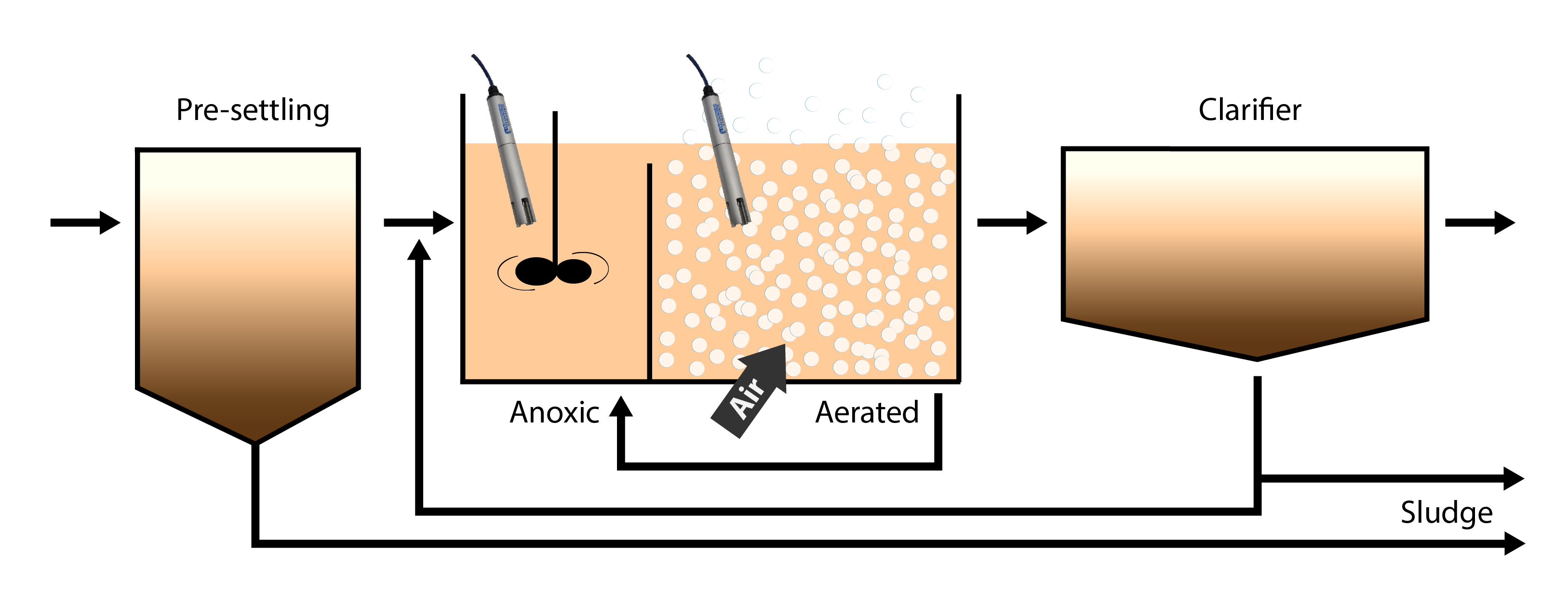
This type of nutrient removal plant is characterized by a pre-denitrification setup utilizing the carbon in the wastewater as electron donor for the denitrification. Normally denitrification and nitrification take place in separate compartments and nitrate is recirculated back from the nitrification tank to the denitrification tank. If we consider the nitrification and denitrification compartments to be completely mixed, then it will be fairly easy to measure and control N2O in this type of plant. The recirculation plant is characterized by fairly stable conditions and normally changes in processes and concentrations are observed fairly slowly.
In the basic setup, N2O Wastewater Sensors should be placed in the denitrification zone and the nitrification zone, respectively. In the denitrification zone N2O is mainly produced due to lack of carbon or due to low dissolved oxygen, and the produced N2O would subsequently be stripped by aeration in the following nitrification zone if not handled correctly. In the nitrification zone, N2O could be produced by a too low dissolved O2 setpoint or by shock loading with nitrogen. Due to the fairly stable process conditions and a certain degree of load balancing of ammonia by the denitrification tank the main N2O trigger is expected to be low dissolved oxygen.
Measures to reduce the N2O emission involve control of nitrate return flow to the denitrification tank combined with an improved COD/TN ratio, which could be achieved by several measures: Sludge fermentation, removal of nitrogen by side stream processes or addition of an external carbon source.

Sequence Batch Reactor (SBR)
In an SBR reactor the processing of wastewater is done sequential in the same tank. Often several reactors are working together in a cyclic way, so the need for storing the inflow wastewater is limited and a more steady effluent flow is obtained.
Sequencing or sequential batch reactors (SBR) treat wastewater in repeated or sequential batches where measurements from the former batch can provide input to the following batch. The operation of an SBR is based on a fill- and -draw principle, which consists of four steps—fill/mix, react, settle, and decant. These steps can be altered for different operational applications.
During the fill and mixing phase, the basin receives influent wastewater. The influent is mixed during filling with the activated sludge in the reactor, creating an environment for biochemical reactions to take place. Mixing and aeration can be varied during the fill phase to create a denitrification (DN) or nitrification (N) environment. Often the majority of denitrification takes place in the mixed-fill phase when the aeration is off. During the following “react phase” no wastewater enters the basin and the mechanical mixing and aeration units are on. Nitrification occurs by allowing the mixing and aeration to continue. Finally, aeration and mixing are stopped and the activated sludge is allowed to settle before the effluent is decanted and the cycle is repeated.
N2O can normally be monitored and controlled by one N2O sensor in each SBR-reactor.
Emission is calculated from knowledge about the kLa-value of the aeration system.
Regarding the control of the N2O emission, our experience is still limited. However, like for recirculation plants it looks like a sufficient COD/TN ratio is important, which ensures a complete denitrification before moving on to the nitrification step. In the nitrification step a low DO should be avoided, and in order to not impose too high variations in the ammonia level, several switches between N/DN within the same batch.

Are you ready to measure nitrous oxide emissions?
Get in touch today and learn how to get started.
